AeroSol · centrifugal compressor design
Design and simulate your compressor at the highest fidelity, before CFD.
AeroSol is a high-fidelity solver for centrifugal compressor aerodynamic design. One duty point goes in, and one geometry carries it the whole way: preliminary sizing, a throughflow solve, a stacked quasi-3D field, a fast structural check on the blade that came out of it, and an agent-driven optimiser that moves the design rather than only reporting on it. Accurate enough that CFD is only ever spent on the designs that have earned it.
A design platform
agents can actually drive.
Sizing, blade generation, throughflow, blade-to-blade: these are the methods turbomachinery design is built on, and they have earned that place. The difficulty has never been the physics. It is that each method usually lives in a program of its own, so a design spends its week being carried between them, and when two of them disagree nobody can say which one to believe.
AeroSol solves all of them on one geometry, in one program, from the equations up. That is what an agent can drive: no file hand-off, no format to translate, no step that needs a person in the middle. State the duty once and the loop runs itself, a hundred complete design passes where moving files by hand gives you one.
AI-driven agentic workflow
Four agents, one loop,
and nobody waiting on you.
You do not drive AeroSol module by module. You state what the machine has to do, and a project manager puts three specialist agents on it, one for intent, one for design and one for verification, with a fourth agent watching all three. When the verification does not hold, it is not patched. It goes back to the beginning and the whole chain runs again.
Project manager
Holds the brief and decides what finished means. It dispatches the three specialists, reads what comes back, and refuses a design that does not meet the duty it was given.
Intent & inputs
Reads what you are trying to build, not just the numbers you typed. Duty, working fluid, speed limit, envelope and the constraints you would have argued about anyway become a bounded, solvable set of inputs.
Design & exploration
Runs the preliminary design, then sweeps the design space and refines until the ranking stops moving. Takes the winner off-design and builds its performance map: surge wall, choke wall, efficiency islands.
Verification
Puts the chosen geometry through the throughflow solver for the first real performance numbers, then the 3-D solver for Mach, pressure and loading across span and along the meridional sections.
Optimisation agent
The one that closes the loop. It is in conversation with all three. When Agent 03's throughflow or 3-D field does not meet the brief, it does not patch the blade and move on. It goes back to Agent 01, changes the inputs, and runs the whole chain again.
Every pass is a complete machine, not a lookup and not a surrogate. That is why the loop can afford to reject one and start over, and why a day's work now looks like five to ten times the design passes an engineer gets through by hand.
Design space
Every dot is a machine
that was actually solved.
The agents do not guess where the good designs are. They go and find out, then come back and search harder where the answers were good. What you see is the shape of your own design space, and the one point in it worth building.
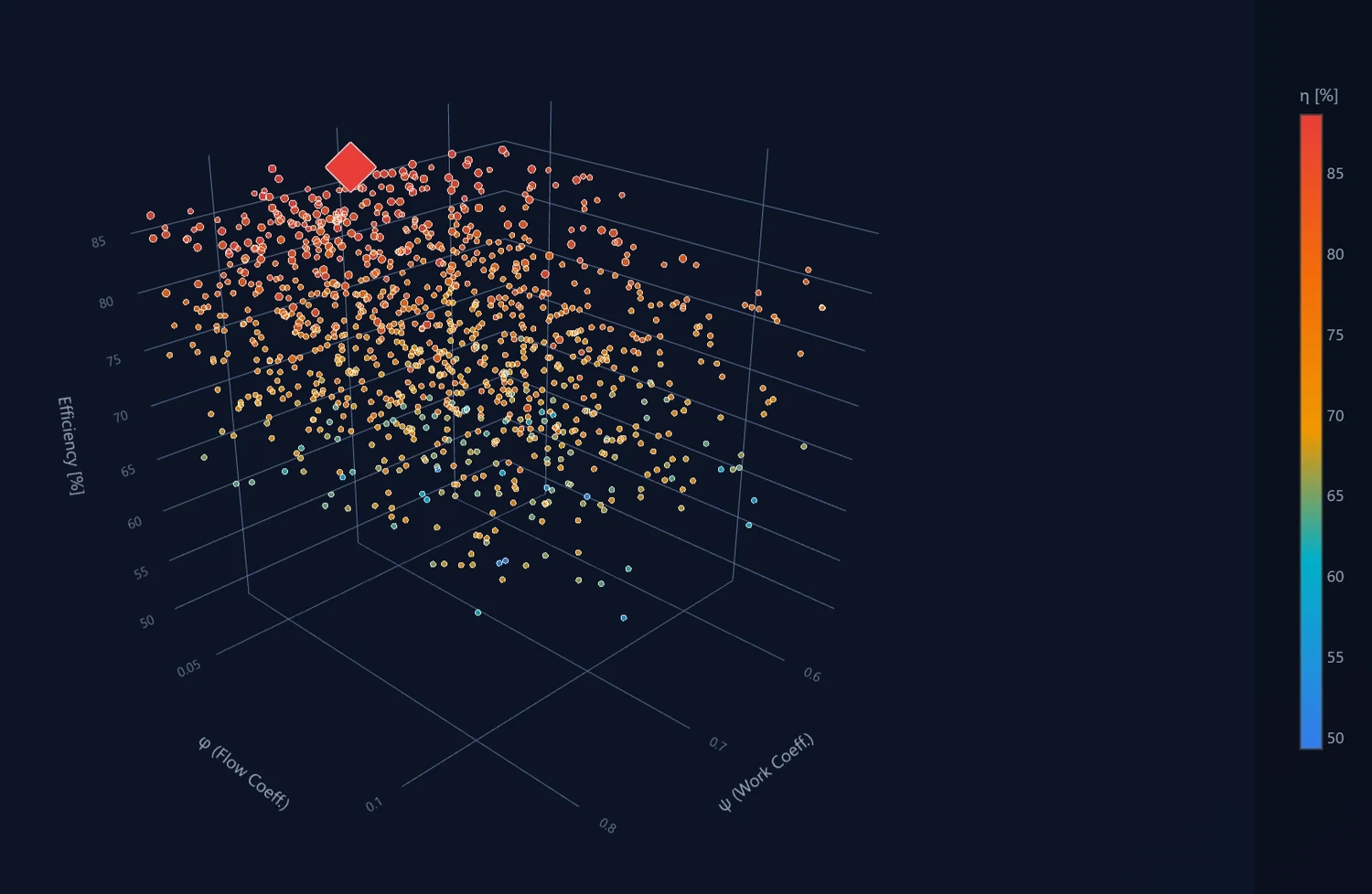
Monte-Carlo search over work and flow coefficient, coloured by efficiency. Red diamond: the best design found.
One geometry, every solver
The design moves itself
from solver to solver.
Preliminary mean-line design, the streamline-curvature throughflow solver and the quasi-3D blade-to-blade field all read the same geometry. Moving between them is automatic: there is no export, no re-drawing and no format to reconcile, because the blade you shape is handed to each solver as it stands. Change a control point and the whole chain re-solves in seconds.
One operating point, fully solved.
Pressure ratio, efficiency, power and tip speed, with specific speed, head and flow coefficient beside them, reported in the conventions a turbomachinery team already works in so the numbers go straight next to your own. Underneath, the flowpath those numbers came from, every radius and blade angle on the drawing.
Shape it like a blade, not like a spreadsheet.
Meridional contour, blade-to-blade wrap, angle and thickness distributions: four synchronised views with draggable control points. Drag one, and the blade beside it re-forms: every solver downstream is already reading the new shape.
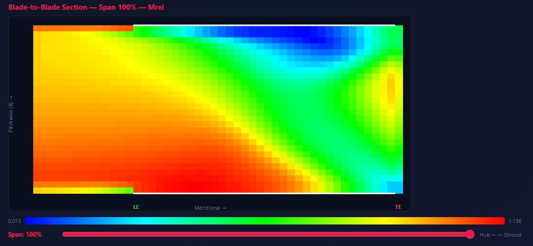
The passage, resolved hub to shroud.
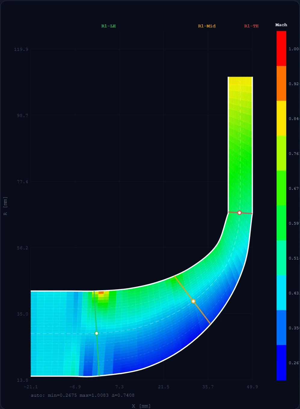
The meridional grid on the left is the passage the solver was handed: hub and shroud stations, the rotor region, the leading- and trailing-edge normals. The field on the right is what came back: a streamline-curvature solve with radial equilibrium, showing where the flow accelerates and where the inducer is about to run out of margin.
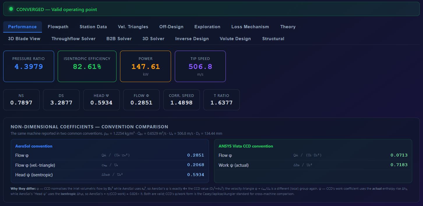
The flow field
Hub to shroud,
in one drag.
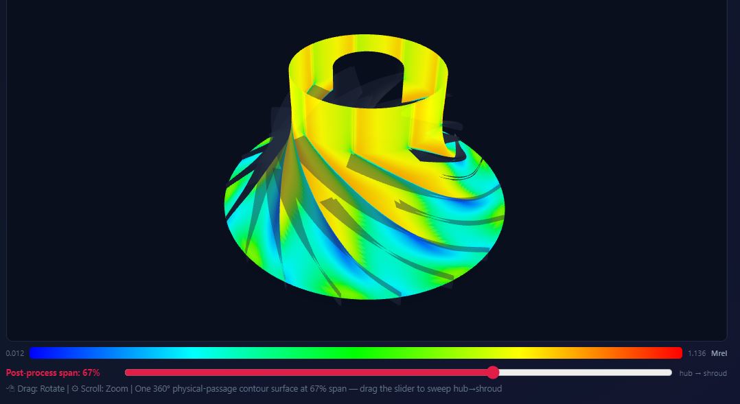
The passage surface is not a picture. It is the solution, post-processed at whatever span you point at, so the loading you argue about is the loading the solver actually produced.
Read the map
Where the machine lives,
and where it stops.
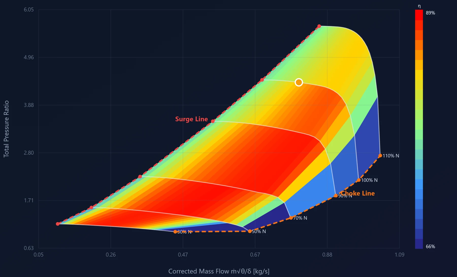
Pick a point on the map
Every boundary on this chart was computed from the same geometry the agents produced. Nothing here was drawn by hand.
Structural
Find out it will not hold
while you can still change it.
The blade the aero design produced is the blade the stress model pulls: its shape, its thickness distribution, its splitter placement, all of it. Pick a material, and the von Mises field, the root stress and the safety factor come back in the same session. Thin the trailing edge, take some twist out, and watch every one of them move.
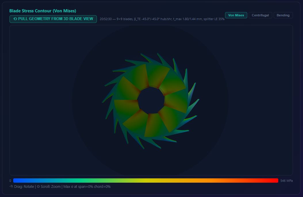
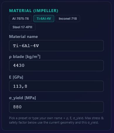
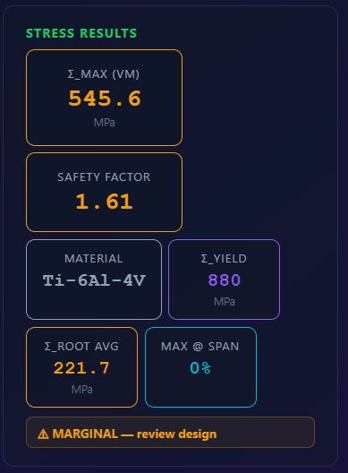
Change the alloy and the whole panel re-reads. The tool tells you when a design is marginal rather than letting you find out later. It is beam theory for screening and Campbell maps, not a finite-element run, which the tool also says out loud.
Accuracy
As close to the truth
as you can get before you mesh.
AeroSol is not a faster CFD. It is the thing that makes CFD worth running, and it earns that by being checkable, by agreeing with itself, and by saying so when it is not sure.
Three solvers, one geometry
Mean-line, streamline-curvature throughflow and a stacked quasi-3D field all run on the identical blade. Where they agree, you can move. Where they part company, you have found the thing to mesh.
Empiricism you can argue with
Slip, diffusion, blade loading, clearance, disc friction, boundary layers: every correlation is the published one, named in the tool, in a single catalogue with each coefficient marked as literature, calibrated, numerical or geometric.
Checked against machines other people measured
The regression suite runs open benchmark impellers and a published transonic stage on every build, and the real-gas model is checked against reference equations of state. The reports ship with the tool.
Worked example: NASA CC3
One machine, entered as built,
against its own measured speed line.
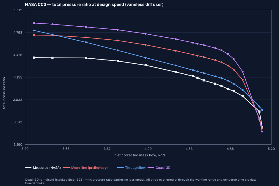
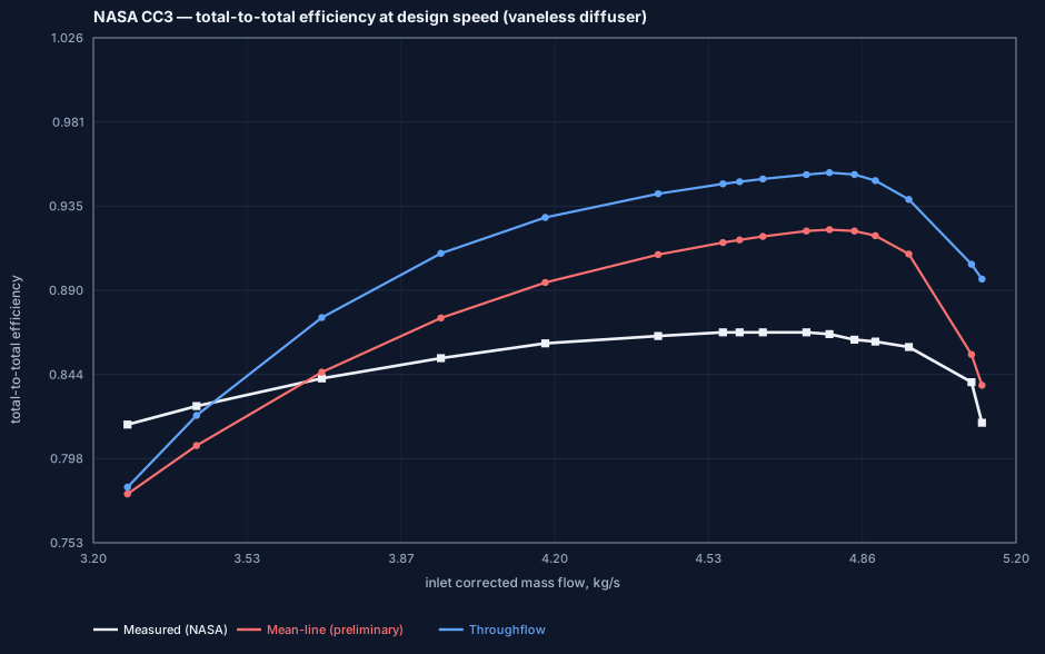
CC3 is NASA's 4:1 transonic centrifugal compressor. Its geometry and its measured performance are both published, which makes it one of the few machines anyone can check a solver against. It was entered into AeroSol as built, in the vaneless-diffuser version, and its design speed line was run through every solver in the chain, with nothing tuned to the answer afterwards.
The shape comes out first
All three follow the measured characteristic: pressure ratio rolling off toward choke, efficiency peaking and falling away on either side of it. Getting that shape out of geometry alone, with no map to interpolate, is the part that is actually hard.
The level is not closed
Through the working range every solver reads high on pressure ratio, converging onto the data toward choke. On efficiency both the mean-line and the throughflow sit above the measurement. That gap is real, it is visible on the chart, and the tool does not smooth it away.
Nothing was fitted to this
The coordinates were read out of NASA CR-204134 and checked by twelve independent geometry tests. The measured line was recovered from the report figure's own vector content rather than digitised by eye. No coefficient was moved to improve the match.
The quasi-3D solver appears in the pressure-ratio chart only: it is inviscid, so its isentropic efficiency is identically 1.000, a number the tool declines to report. Both charts are the validation script's own output; the site restyles them to its palette and removes that one meaningless curve. No measured or predicted point has been touched.
Second worked example: CFD on an AeroSol design
The other direction: a machine designed here,
then meshed and solved.
CC3 checks the tool against a machine somebody else built and measured. This one runs the other way. A compressor was designed in AeroSol, exported, and rebuilt in CFD as the same geometry, and the whole design speed line was solved again from the mesh. Nothing was adjusted in between, which means the two answers are allowed to disagree, and where they do the chart says so.
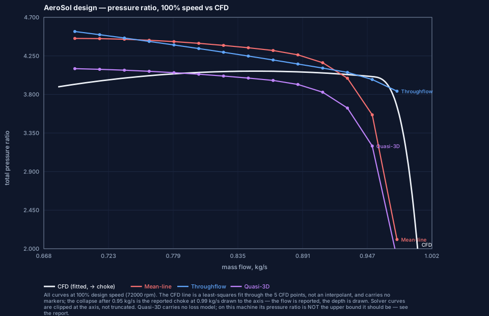
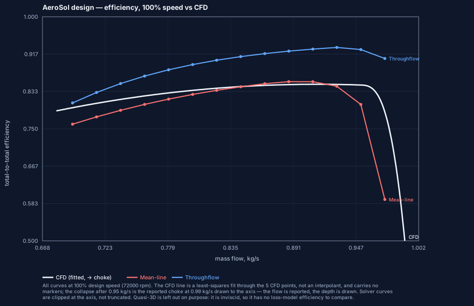
Both charts are at 100% design speed, 72 000 rpm. The CFD line is a least-squares fit through five solved points, and the fall at the right is its reported choke drawn to the axis. On efficiency the mean-line lands on the CFD line: it peaks at 0.855 where CFD peaks at 0.849, within about 0.02 kg/s of the same flow. The throughflow reads five to eight points high, widening toward choke. On pressure ratio both read high, by around ten per cent at low flow, closing to a few per cent as the machine opens up. The quasi-3D curve sits almost on the CFD line, which is not the good news it looks like: it carries no loss model, so it should be above everything else on the chart.
Blade to blade, 50% span
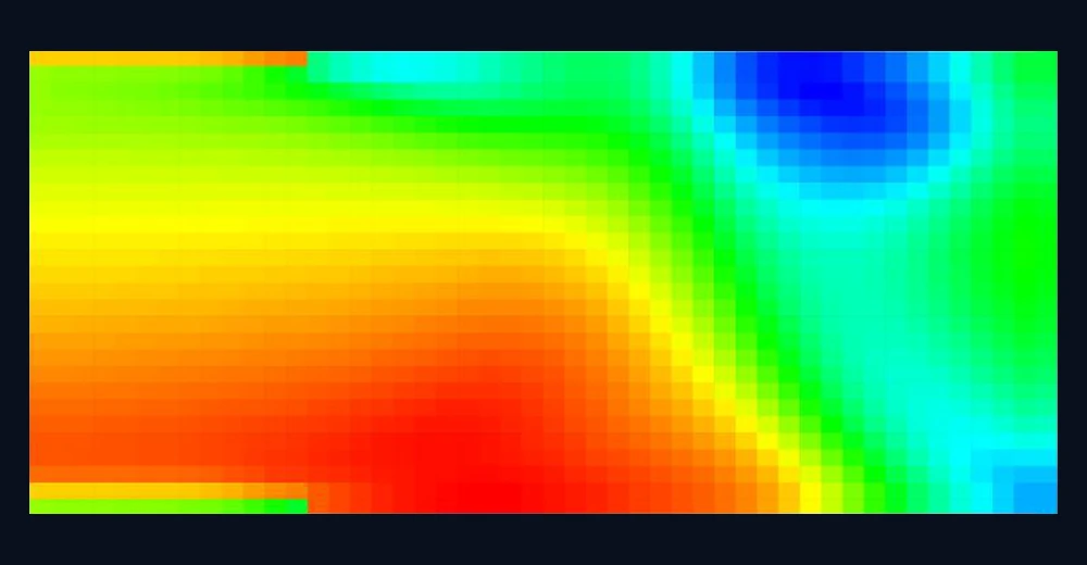
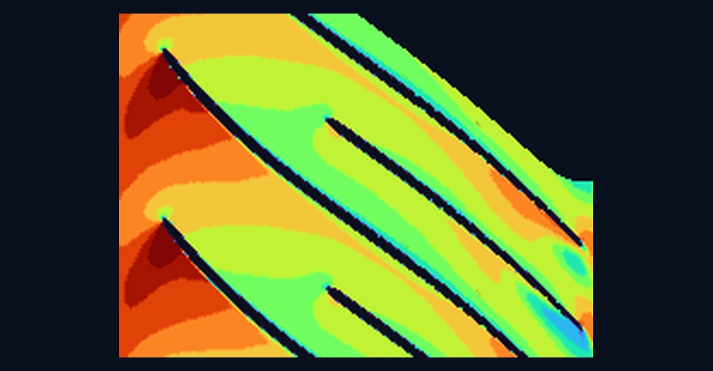

Relative Mach at half span, meridional left to right, pitchwise up the frame. Both were exported on the same scale, the one drawn under them, so a colour means the same thing in each. The loading has the same shape in both: acceleration along the suction surface off the leading edge, deceleration through the passage, and the low-momentum region carried to the trailing edge. The CFD passage carries a splitter and AeroSol's does not, which is the largest single difference visible here; modelling it is the next piece of work on the quasi-3D solver.
Near the shroud, on the passage itself
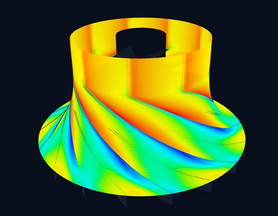
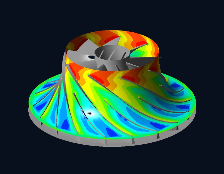

The same quantity again, both on the scale under them. The cameras and the shading are not the same, so what is worth reading is where the flow is fast and where it is not: both put the same low relative Mach streak down the suction side of every blade, and the same fast band around the shroud toward the exit. AeroSol is drawing its own passage surface at 95% of the passage; the CFD is its solution on the blades and hub of the same machine. The CFD frame is mirrored left to right so that both turn the same way. Mirror a machine and its flow field mirrors with it, so each blade keeps its own suction and pressure side; nothing else in the frame is touched.
One geometry, two answers
The mesh was built on the machine AeroSol wrote, not on a cleaned-up version of it, and no coefficient was moved once the CFD came back. The agreement in shape, and the disagreement in level, are both what the tool produced on its first run.
Where it is worth trusting
Efficiency out of the mean-line, and the shape of the loading out of the quasi-3D, are close enough to choose between candidates on. Pressure ratio reads high, so a design picked on level alone will disappoint the mesh, and that is exactly the call CFD is for.
The splitter is the next piece
The quasi-3D passage here has no splitter in it while the machine does, which costs it most through the second half of the passage, where in the CFD the splitter is doing the work. Modelling it is the next thing on this solver, and it is where most of the remaining difference should go.
And what it is not
- Not CFD. It is inviscid where it says inviscid, and the quasi-3D field shows you the loading, not certification.
- The structural module is beam theory for screening and Campbell maps, not finite-element stress, and it says so in the tool.
- Calibration rests on a few measured machines. Where the tool extrapolates, it says so rather than smoothing it over.
- It is a pre-CFD tool. It exists so the CFD you do run is spent on candidates that deserve it.
This block is here on purpose. A tool that will not tell you its limits has not told you anything.
How it ships
A desktop application.
Nothing leaves your machine.
Windows, macOS and Linux. No licence server, no upload, no cloud queue. Your geometry stays yours, and when a design is ready it leaves as STEP surfaces and BladeGen/TurboGrid-compatible curves, straight into the mesher you already use.
About
An engineer enthusiastic
about aerodynamics.
AeroSol is built by Anıl Berk Atalar, an independent researcher who has spent more than ten years on aerodynamic and thermal turbomachinery design and analysis, using CFD and optimisation. The solvers, the agent loop and every validation study on this site are his own work.
It is an independent, non-commercial research project. It is not affiliated with, funded by or endorsed by any company, university or institution, and nothing on this site is anyone else's position. The work started in late 2018 and it continues in the open: what holds up is shown with the evidence beside it, and what does not is written down as a limit.
If you have a machine, a measured map or a design case worth putting through it, the address below reaches the person who wrote the code.
Pilot study
Half an hour.
Your duty point, live.
A pilot study is a thirty-minute session with your team. You bring a machine you are actually trying to design; we take it through AeroSol in front of you: sizing, blade, map, stress. You keep whatever comes out of it. No slide deck, and no obligation at the end of it.